How to make your first robot
What kind of robot?
In this tutorial we want to make a robot that can drive a pre defined route and surround objects blocking the route.
What you need
This is a list of really everything you need, but if you will do more projects, this includes a lot of essentials you will need for every project.
Important: This are only links for the German products.
1. Electronics
- Core MAX10
- Shield MAX10
- Motor Extension
- Level Shifter Extension
- 2 Motors with wheel and encoder*
- 1-5 Ultrasonic sensors*
- 1 12V battery holder*
- 8 AA Batteries*
- 1 Jumper connector kit*
2. Chassis
3. Tools
*This links are Affiliate Links. By purchasing with them you support us and our work, because we get a part of the revenue as commission. You still pay the same price.
If you want to work on FPGA projects in a team, you can check out ONE WARE Studio!
The Chassis
Be creative and invent your own chassis. The easiest way is probably to take some wood plank* and mount the motors. If you have the same motors as me*, take the mount, drill some holes with a cordless screwdriver* and a 3mm drill bit and secure it with the M3 screws. This is how my solution looks like:
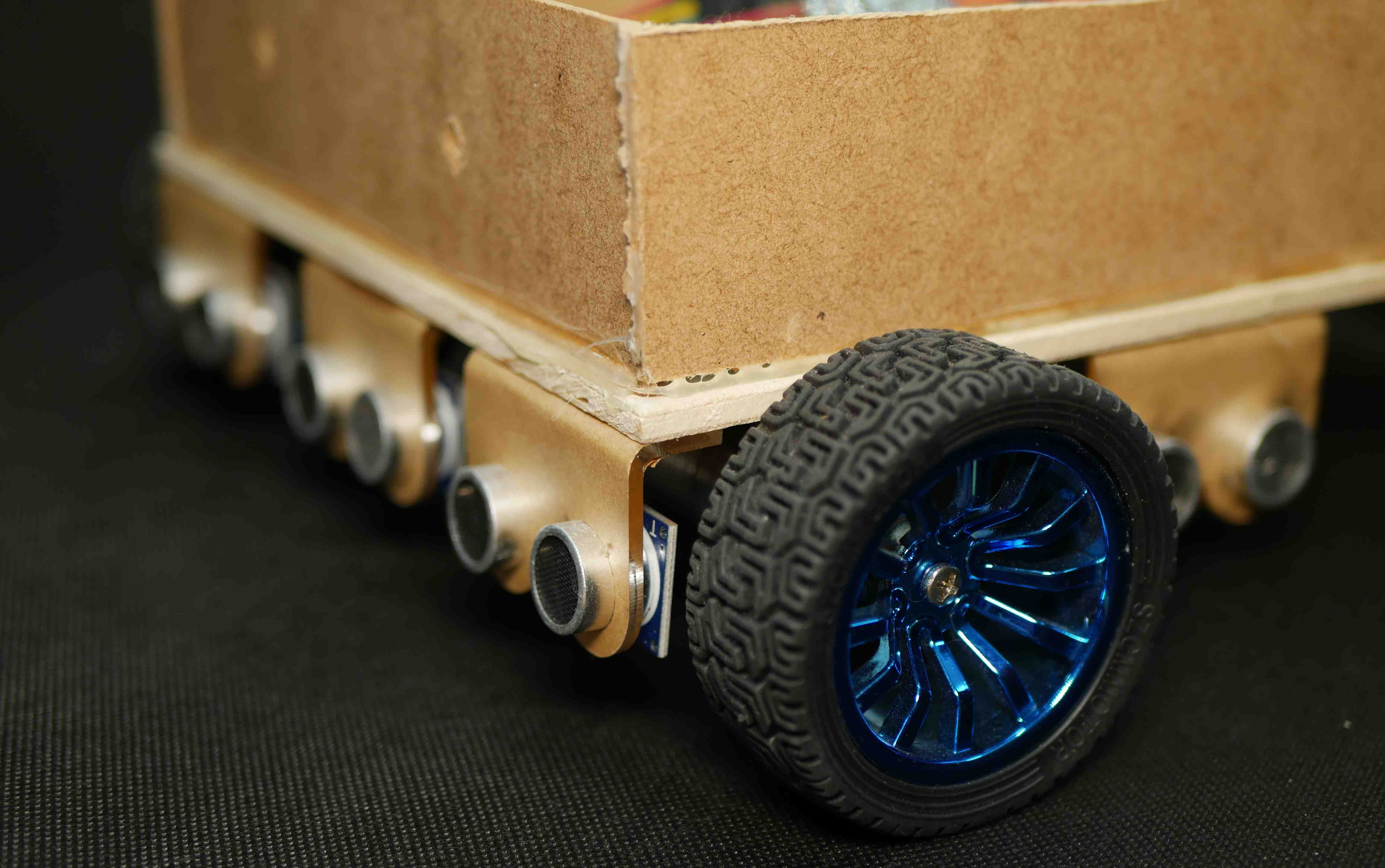
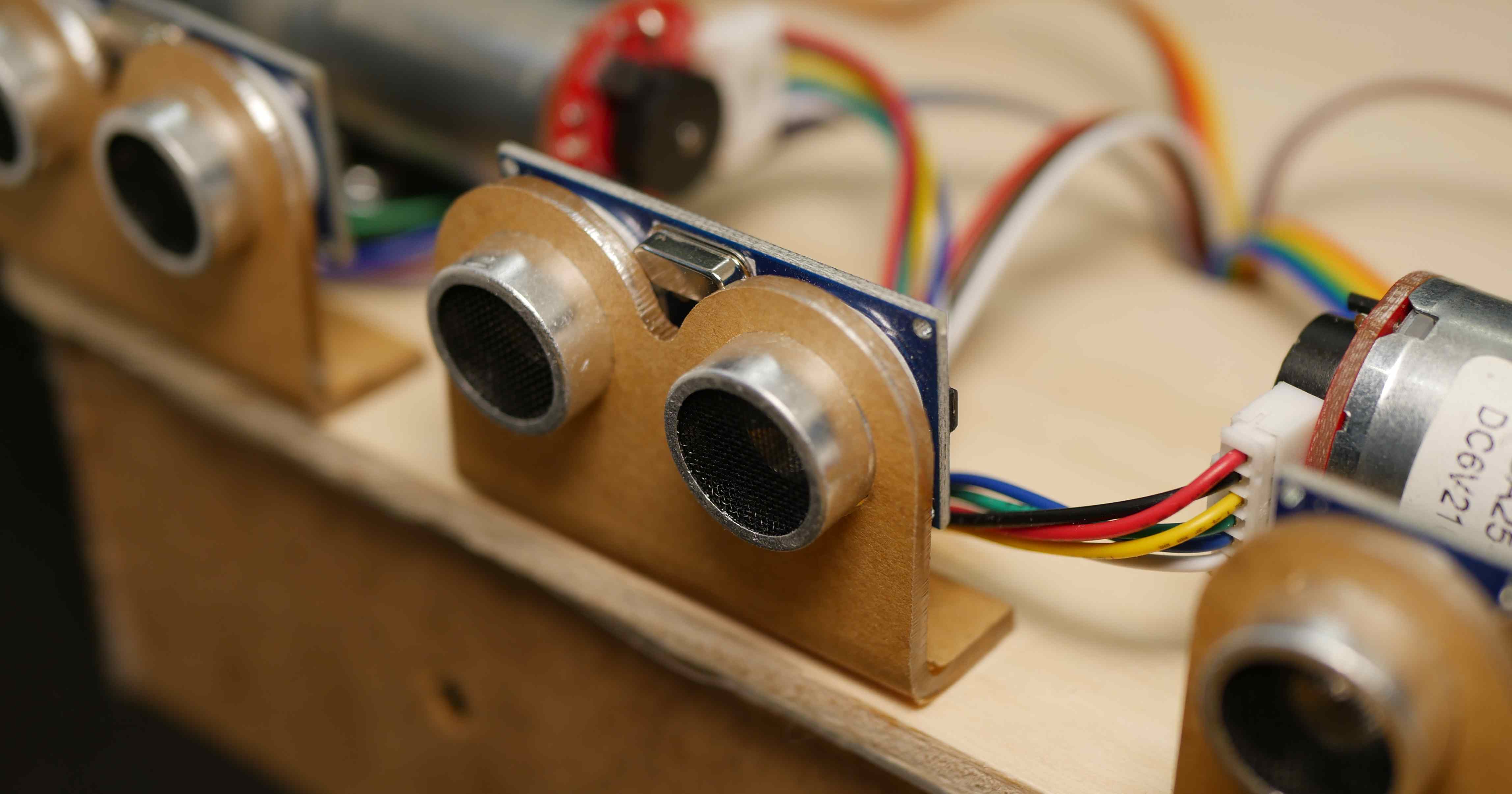
The same way you can mount the ultrasonic sensors*. Ideally you have two that look to the sides and one or more that look forward, so they can detect if the robot hit something. If you bought a set of 5 sensors with mount, you can arrange them like this:
With VHDPlus Hardware
Electronics
Connect the Core, Shield, Motor and Level Shifter extensions together like that:

The standard motors with encoder can be connected directly to the Motor Extension.
|Red|    -> O1.1
|Black|  -> GND
|Yellow| -> E1.1
|Green|  -> E1.2
|Blue|   -> 3.3V
|White|  -> O1.2
To connect the ultrasonic sensors, connect the VCC, GND and Trig pins of the ultrasonic sensors together with a breadboard and connect each Echo pin and the combined VCC, GND and Trig pins with the Level Shifter Extension.
Software
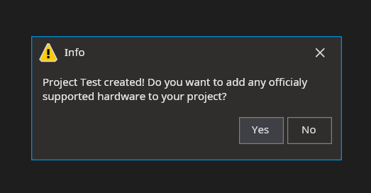
Now you can open the VHDPlus IDE, create a new project, select the Shield, Motor and Level Shifter with ultrasonic sensor modules. The code is generated for you and the pins are selected automatically.
Watch this video to see the full tutorial: currently not available
With Standard Hardware
Electronics
Motors
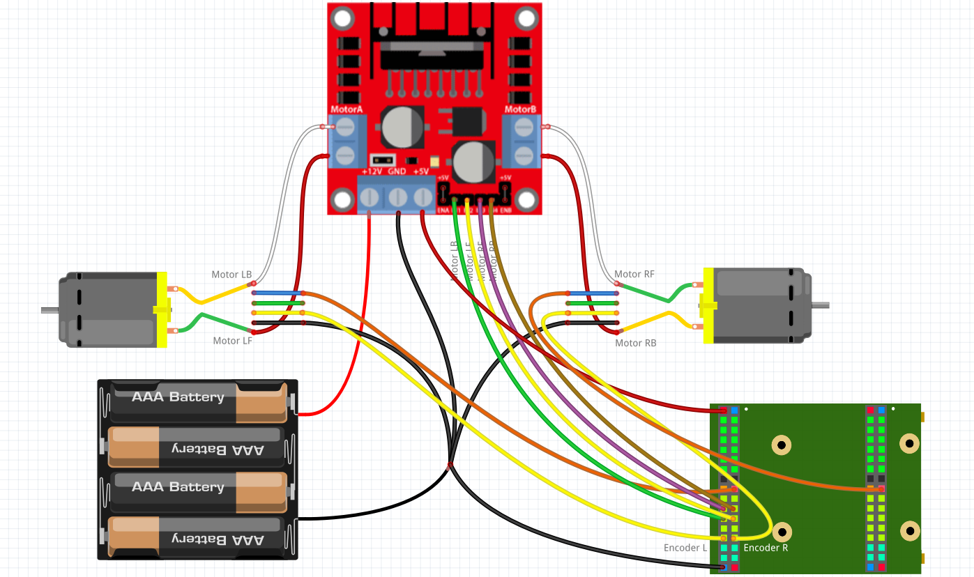
First we connect the motors like that:
 You can use the breadboard and jumper cables* to make the connections. Use the Jumper connector kit* and the D-SUB crimping tool* to be able to plug the motor cables in the breadboard. You can see how to do that here.
The yellow cables and the motor driver* inputs should be connected with the FPGA I/Os'. The Battery* is connected with GND and +12 of the motor driver and GND and +5V has to be connected with GND and VIN of the FPGA. The blue cables of the motors have to be connected with 3.3V and the black cables with GND. Finally the motors have to be connected with the motor outputs of the motor driver.
Ultrasonic sensors
Connect the ultrasonic sensors like that:
 Connect the GND and VCC pins of the ultrasonic sensors with GND and VBUS of the Core Board.
Important: Because the ultrasonic sensors work with 5V, its important to make the Echo output of the sensor 3.3V. So I used a voltage divider. You have 5V output on the top, then two 1k resistors* in parallel (this makes 0.5k) connect this with the 3.3V output and then one 1k resistor that connects that with GND.
Finally all Echo outputs should be connected through the voltage divider (or level shifter) with the FPGA. The Trigger pins should be connected together with one FPGA pin.
Debugging
If you want to get information about the current state of the route, you can use the example from GitHub connect an HC-05 Bluetooth module* with the RX and TX I/Os'. This lets you connect your phone with the module and get live updates to a Serial Bluetooth Terminal app.
The software
Create a new project and import the Motor library folder, the PWM library and the Ultrasonic library. Now you can copy this example:
Main
(
    Encoder_L           : IN STD_LOGIC;
    Encoder_R           : IN STD_LOGIC;
    Motor_LF            : BUFFER STD_LOGIC;
    Motor_LB            : BUFFER STD_LOGIC;
    Motor_RF            : BUFFER STD_LOGIC;
    Motor_RB            : BUFFER STD_LOGIC;

    Trigger             : OUT STD_LOGIC;
    EchoL               : IN STD_LOGIC;
    EchoF               : IN STD_LOGIC;
    EchoF1              : IN STD_LOGIC;
    EchoF2              : IN STD_LOGIC;
    EchoR               : IN STD_LOGIC;

    btn                 : in STD_LOGIC;
    RX                  : IN STD_LOGIC;
    TX                  : BUFFER STD_LOGIC;
)
{
    --Motor controller settings
    CONSTANT CLK_Frequency                        : NATURAL := 12000000; --12MHz
    CONSTANT Motor_Controller_Holes_In_Disk       : NATURAL := 11;    --11 = 11 Changes for one encoder turn
    CONSTANT Motor_Controller_Gear_Ratio          : NATURAL := 34;    --34 = 1:34 Gear ratio
    CONSTANT Motor_Controller_Wheel_Circumference : NATURAL := 204;   --204 = 65mm diameter*pi = 204mm circumference
    CONSTANT Motor_Controller_Max_Length          : NATURAL := 10000; --10m maximum route step length
    CONSTANT Motor_Controller_Route_Steps         : NATURAL := 10;    --10 steps maximum

    Process Route_Start_Process ()
    {
        --If object is closer than 12cm, the robot tries to surround it
        If(Ultrasonic_Controller_Dist_F < 12 OR Ultrasonic_Controller_Dist_F1 < 12 OR Ultrasonic_Controller_Dist_F2 < 12)
        {
            Motor_Collision <= '1';
        }
        Else
        {
            Motor_Collision <= '0';
        }

        --Start route by pressing button
        Motor_Route_Start <= btn;

        --Define Route to 80cm + 20cm + turn 90° left + 50cm
        Motor_Route_L      <= (800,  200, -155, 500, 0, 0, 0, 0, 0, 0);
        Motor_Route_R      <= (800,  200,  155, 500, 0, 0, 0, 0, 0, 0);
        --Set speed to 200 for driving streight and 170 for turns
        Motor_Route_Speed  <= (200,  200,  170, 200, 0, 0, 0, 0, 0, 0);
        --Set number of route steps
        Motor_Route_Length <= 4;
    }

    SIGNAL Motor_Collision           : STD_LOGIC;
    SIGNAL Motor_Route_Start         : STD_LOGIC;
    SIGNAL Motor_Route_L             : Route_Array (0 to Motor_Controller_Route_Steps-1);
    SIGNAL Motor_Route_R             : Route_Array (0 to Motor_Controller_Route_Steps-1);
    SIGNAL Motor_Route_Speed         : Route_Array (0 to Motor_Controller_Route_Steps-1);
    SIGNAL Motor_Route_Length        : NATURAL     range 0 to Motor_Controller_Route_Steps;
    SIGNAL Motor_Route_Finished      : STD_LOGIC;
    SIGNAL Motor_Route_Error         : STD_LOGIC;
    SIGNAL Motor_Route_State         : NATURAL range 0 to 255;

    NewComponent Motor_Route_Drive
    (
        CLK_Frequency       => CLK_Frequency,
        Route_Steps         => Motor_Controller_Route_Steps,
        Max_Length          => Motor_Controller_Max_Length,
        --Left motor has to turn -15.5cm and right motor 15.5cm at speed 170/255 to make 90° with my robot
        Turn_Length         => 155,
        Turn_Speed          => 170,
        --Drive 15cm at speed 200/255 back when object in front of robot
        Back_Length         => 150,
        Back_Speed          => 200,
        --Has sensors on the right and left, so Side_Distances is true
        Side_Distances      => true,
        --Checks every 10cm if route is clear (drives 10cm further if yes)
        Check_Distance      => 100,
        Holes_In_Disk       => Motor_Controller_Holes_In_Disk,
        Gear_Ratio          => Motor_Controller_Gear_Ratio,
        Wheel_Circumference => Motor_Controller_Wheel_Circumference,
        --Don't check if wheel is turning for fist 500ms
        Error_Delay         => 500,
        --Correct speed every 10 encoder edges
        Correction_Step     => 1,
        Correction_Cycles   => 10,
        --If 2cm length difference, subtract 25/255 speed
        Length_Corr_Step    => 25,
        Max_Length_Diff     => 20,
        --Increase 10cm 100/255 speed for acceleration
        Accel_Length        => 100,
        Accel_Speed         => 100,
        --Decrease 10cm 100/255 speed for braking
        Brake_Length        => 100,
        Brake_Speed         => 100,
        --2s for one wheel turn is minimum speed while accelerating and braking + 20s for wheel turn to trigger error
        Max_Turn_Time       => 2000,

        Reset               => '0',
        Encoder_L           => Encoder_L,
        Encoder_R           => Encoder_R,
        Motor_LF            => Motor_LF,
        Motor_LB            => Motor_LB,
        Motor_RF            => Motor_RF,
        Motor_RB            => Motor_RB,
        Collision           => Motor_Collision,
        Distance_F          => Ultrasonic_Controller_Dist_F,
        Distance_L          => Ultrasonic_Controller_Dist_L,
        Distance_R          => Ultrasonic_Controller_Dist_R,
        Route_Start         => Motor_Route_Start,
        Route_Finished      => Motor_Route_Finished,
        Route_L             => Motor_Route_L,
        Route_R             => Motor_Route_R,
        Route_Speed         => Motor_Route_Speed,
        Route_Length        => Motor_Route_Length,
        Route_Error         => Motor_Route_Error,
        State               => Motor_Route_State,
    );

    SIGNAL Ultrasonic_Controller_Dist_L             : NATURAL   range 0 to 1000;

    NewComponent Ultrasonic_Controller
    (
        CLK_Frequency    => CLK_Frequency,
        Update_Frequency => 15,

        Reset            => '0',
        Trigger          => Trigger,
        Echo             => EchoL,
        Dist             => Ultrasonic_Controller_Dist_L,
    );

    SIGNAL Ultrasonic_Controller_Dist_F             : NATURAL   range 0 to 1000;

    NewComponent Ultrasonic_Controller
    (
        CLK_Frequency    => CLK_Frequency,
        Update_Frequency => 15,

        Reset            => '0',
        Echo             => EchoF,
        Dist             => Ultrasonic_Controller_Dist_F,
    );

    SIGNAL Ultrasonic_Controller_Dist_F1            : NATURAL   range 0 to 1000;

    NewComponent Ultrasonic_Controller
    (
        CLK_Frequency    => CLK_Frequency,
        Update_Frequency => 15,

        Reset            => '0',
        Echo             => EchoF1,
        Dist             => Ultrasonic_Controller_Dist_F1,
    );

    SIGNAL Ultrasonic_Controller_Dist_F2            : NATURAL   range 0 to 1000;

    NewComponent Ultrasonic_Controller
    (
        CLK_Frequency    => CLK_Frequency,
        Update_Frequency => 15,

        Reset            => '0',
        Echo             => EchoF2,
        Dist             => Ultrasonic_Controller_Dist_F2,
    );

    SIGNAL Ultrasonic_Controller_Dist_R             : NATURAL   range 0 to 1000;

    NewComponent Ultrasonic_Controller
    (
        CLK_Frequency    => CLK_Frequency,
        Update_Frequency => 15,

        Reset            => '0',
        Echo             => EchoR,
        Dist             => Ultrasonic_Controller_Dist_R,
    );
}
This example defines a simple route and by pressing the button the robot starts driving.
Make sure to set Holes_In_Disk, Gear_Ratio and Wheel_Circumference according to your motor and wheel. With Accel_Length, Accel_Speed, Brake_Length and Brake_Speed you can make driving smoother by accelerating and braking. Also check out Turn_Length, Turn_Speed, Back_Length and Back_Speed to optimize the object surrounding.
You can find the full example here.
Conclusion
The hard part is definitely the hardware and wiring, but if you finished this tutorial the real fun can begin. Try to make this your own project and e.g. let the robot bring you things. Connect it with WIFI and use and app to control it or connect it with Alexa to say "Alexa bring me the trashcan" and the robot comes to you. In the internet you find a lot of information to expand your project.
Here are other projects with the motor controller:
Possible problems
First make share that everything is connected like described and that you chose the correct pins of your FPGA.
1. Only one wheel turns
- When you e.g. connect the encoders correctly, but flip the right and left motor output, the robot will try to correct the speed and end up in having only one wheel turn.
- Turn the wheel of the spinning motor and check if the encoder input changes it's state (e.g. by connecting the encoder input with the led). If not, check every part between encoder and FPGA, if everything is connected. You can use a multimeter and check if the voltage changes between 0 and 3V when you turn the wheel.
2. No wheel turns
- Make sure that Route_Steps is not 0 and that the lengths are > 0.
Error_Delayis maybe too low (ifCLK_Frequencyis correct this is inms)- Make sure that there is a signal at the motor output pins (with a multimeter or by connecting the signal with an LED).
- If there is an output, check if the motor driver is working, by connecting the input pin directly with 3.3V. Check with a multimeter the voltages of the motor driver in and outputs. If it outputs voltage, check the connection between driver and motor. Otherwise maybe try a different motor driver.
- If there is not output at the motor pins, check if you chose the correct pins and that Route_Start changes from '0' to '1' at the beginning (you have to press the button to start driving).
3. Both wheels turn, but in opposite direction
Check which wheel runs backwards and switch the connection of the M1 and M2 motor driver output.
4. The wheels are working but don't drive the desired lengths
Check the Holes_In_Disk, Gear_Ratio and Wheel_Circumference parameters again. Holes_In_Disk is the number of changes from '0' to '1' of the encoder input for one wheel turn. Gear_Ratio can be found in the motor description (1:90 = 90). Wheel_Circumference is the diameter of the wheel (in mm) times 3.14 (pi). Finally check if all your distances are in mm (1m = 100cm = 1000mm).
5. The robot doesn't drive straight
With Correction_Step, Correction_Cycles, Length_Corr_Step and Max_Length_Diff you can adjust this.
- If the encoder spins very quickly and the speed changes to heavily, increase
Correction_CyclesandMax_Length_Diffand decreaseCorrection_StepandLength_Corr_Step. - If the encoder is e.g. connected directly with the wheel and spins not that quickly, decrease
Correction_CyclesandMax_Length_Diffand increaseCorrection_StepandLength_Corr_Step. - If this doesn't help, you can try to change the
Debounce_Cyclesconstant in theMotor_Route_Drivelibrary.
6. The robot doesn't drive all route parts
- Check if
Route_Stepsis correct. - Maybe
Brake_Speedis too high and the motor hasn't enough power at the end
7. The robot drives the wrong route
- Check if Collision is '0'
Error_Delayis maybe too low (ifCLK_Frequencyis correct this is inms)- Maybe the left and right motors are switched
- check if the lengths are correct (see 4.)
8. The robot doesn't stop precisely enough
You can set the length and amount of speed difference (0-255) with that the motor should brake. Brake_Length sets the length at the end of a route part, in that the robot should decelerate (in mm). With Brake_Speed you can set how much the robot should brake. Be cautious that the robot has enough power at the end of the route part to finish it.
We hope you enjoyed the tutorial and feel free to check out