Logic Analyzer with PulseView
What is the tutorial about?
In this tutorial you learn how to convert an FPGA into a Logic Analyzer. Because of the high performance, even sample rates of 200MHz and more would be possible. And if you would buy a logic analyzer with this sample rates, you would have to spend more than 100€. With the FPGA you can also modify the sample speed, depth and input channels.
What you need
If you want to work on FPGA projects in a team, you can check out ONE WARE Studio!
Hardware
If you have 3.3V signals to measure, you can just connect the signals with the FPGA pins and the GND pin. If you want to use the FPGA as normal Logic Analyzer, you should add protections to the pins (for example with the 74HC245)
Convert the FPGA into a Logic Analyzer
- Create a new project in the VHDPlus IDE and select Logic Analyzer (Max. Speed) or Logic Analyzer SDRAM (Max. Samples) in the list of example projects
- You can change the baudrate, maximum samples and channels with the parameters of the ols logic analyzer component. Max channels are 32 and the maximum samples 64M for SDRAM and 300K for the standard logic analyzer
- In the ols logic analyzer component you have the uart interface and the logic analyzer that creates the sample clock. You can adapt the PLL for a different sample clock (default: 150MHz for SDRAM and 200MHz for standard). Don't forget to change the parameters for the new clock frequency
- Compile the project and select the pins where you want to have the logic analyzer inputs
- Program the FPGA and select Extras -> Long-Term Programming to save the program on the FPGA
Use the Logic Analyzer
- Go to the serial monitor, select the baudrate (usualy 12Mbaud) and the COM port of your FPGA
- Click on the right button and open the logic analyzer
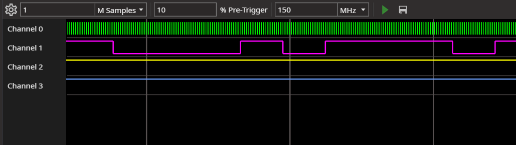
- With the settings button, you can set the maximum sample rate, the trigger and enable the inputs
- Set the number of samples, but this has to be less or equal the number of maximum samples
- Set the percentage of samples before the trigger
- Set the actual sample rate. This will be rounded to a divisor of the maximum sample rate
- And click on the run button. If the logic analyzer doesn't run, either the FPGA is waiting for the trigger or the uart settings are not correct
- You can also click on save to save the data as vcd file
- Right click a line to add a decoder (currently not supported)
We hope you enjoyed the tutorial and feel free to check out